- 您现在的位置:买卖IC网 > Sheet目录3891 > PIC16C72A-20I/ML (Microchip Technology)IC MCU OTP 2KX14 A/D PWM 28QFN
PIC16C62B/72A
1999 Microchip Technology Inc.
Preliminary
DS35008B-page 29
5.2
Timer1 Oscillator
A crystal oscillator circuit is built-in between pins T1OSI
(input) and T1OSO (amplifier output). It is enabled by
setting control bit T1OSCEN (T1CON<3>). When the
Timer1 oscillator is enabled, RC0 and RC1 pins
become
T1OSO
and
T1OSI
inputs,
overriding
TRISC<1:0>.
The oscillator is a low power oscillator rated up to 200
kHz. It will continue to run during SLEEP. It is primarily
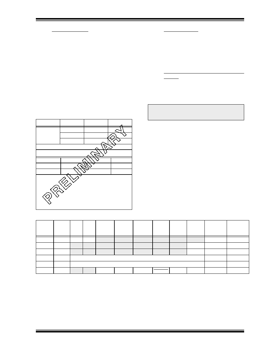
intended for a 32 kHz crystal. Table 5-1 shows the
capacitor selection for the Timer1 oscillator.
The Timer1 oscillator is identical to the LP oscillator.
The user must provide a software time delay to ensure
proper oscillator start-up.
TABLE 5-1
CAPACITOR SELECTION FOR
THE TIMER1 OSCILLATOR
5.3
Timer1 Interrupt
The TMR1 Register pair (TMR1H:TMR1L) increments
from 0000h to FFFFh and rolls over to 0000h. The
TMR1 Interrupt, if enabled, is generated on overflow
and is latched in interrupt flag bit TMR1IF (PIR1<0>).
This interrupt can be enabled by setting TMR1 interrupt
enable bit TMR1IE (PIE1<0>).
5.4
Resetting Timer1 using a CCP Trigger
Output
If the CCP module is configured in compare mode to
generate a “special event trigger" (CCP1M3:CCP1M0
= 1011), this signal will reset Timer1 and start an A/D
conversion (if the A/D module is enabled).
Timer1 must be configured for either timer or synchro-
nized counter mode to take advantage of this feature. If
Timer1 is running in asynchronous counter mode, this
reset operation may not work.
In the event that a write to Timer1 coincides with a spe-
cial event trigger from CCP1, the write will take prece-
dence.
In this mode of operation, the CCPR1H:CCPR1L regis-
ters pair effectively becomes the period register for
Timer1.
TABLE 5-2
REGISTERS ASSOCIATED WITH TIMER1 AS A TIMER/COUNTER
Osc Type
Freq
C1
C2
LP
32 kHz
33 pF
100 kHz
15 pF
200 kHz
15 pF
These values are for design guidance only.
Crystals Tested:
32.768 kHz
Epson C-001R32.768K-A
± 20 PPM
100 kHz
Epson C-2 100.00 KC-P
± 20 PPM
200 kHz
STD XTL 200.000 kHz
± 20 PPM
Note 1: Higher capacitance increases the stability
of oscillator but also increases the start-up
time.
2: Since each resonator/crystal has its own
characteristics, the user should consult the
resonator/crystal manufacturer for appropri-
ate values of external components.
Note:
The special event trigger from the CCP1
module will not set interrupt flag bit
TMR1IF (PIR1<0>).
Address
Name
Bit 7
Bit 6
Bit 5
Bit 4
Bit 3
Bit 2
Bit 1
Bit 0
Value on
POR,
BOR
Value on
all other
resets
0Bh,8Bh
INTCON
GIE
PEIE
T0IE
INTE
RBIE
T0IF
INTF
RBIF
0000 000x
0000 000u
0Ch
PIR1
—
ADIF
—
SSPIF
CCP1IF
TMR2IF
TMR1IF
-0-- 0000
8Ch
PIE1
—
ADIE
—
SSPIE
CCP1IE
TMR2IE
TMR1IE
-0-- 0000
0Eh
TMR1L
Holding register for the Least Significant Byte of the 16-bit TMR1 register
xxxx xxxx
uuuu uuuu
0Fh
TMR1H
Holding register for the Most Significant Byte of the 16-bit TMR1 register
xxxx xxxx
uuuu uuuu
10h
T1CON
—
T1CKPS1 T1CKPS0 T1OSCEN T1SYNC TMR1CS TMR1ON --00 0000 --uu uuuu
Legend:
x
= unknown, u = unchanged, - = unimplemented read as '0'. Shaded cells are not used by the Timer1 module.
发布紧急采购,3分钟左右您将得到回复。
相关PDF资料
PIC16C62B-20I/ML
IC MCU OTP 2KX14 PWM 28QFN
PIC16C770-E/P
IC MCU CMOS A/D 2K 20MHZ 20-DIP
PIC16C770-E/SO
IC MCU OTP 2KX14 A/D PWM 20SOIC
PIC18LC442T-I/PT
IC MCU OTP 8K16 A/D 44TQFP
PIC18LC442T-I/L
IC MCU OTP 8K16 A/D 44PLCC
PIC16F723A-I/ML
MCU PIC 7KB FLASH XLP 28-QFN
PIC16F1826-I/SS
IC PIC MCU FLASH 2K 20-SSOP
PIC16F1825-I/ST
MCU PIC 14K FLASH 1K 14TSSOP
相关代理商/技术参数
PIC16C72A-20I/SO
功能描述:8位微控制器 -MCU 3.5KB 128 RAM 22 I/O RoHS:否 制造商:Silicon Labs 核心:8051 处理器系列:C8051F39x 数据总线宽度:8 bit 最大时钟频率:50 MHz 程序存储器大小:16 KB 数据 RAM 大小:1 KB 片上 ADC:Yes 工作电源电压:1.8 V to 3.6 V 工作温度范围:- 40 C to + 105 C 封装 / 箱体:QFN-20 安装风格:SMD/SMT
PIC16C72A-20I/SP
功能描述:8位微控制器 -MCU 3.5KB 128 RAM 22 I/O RoHS:否 制造商:Silicon Labs 核心:8051 处理器系列:C8051F39x 数据总线宽度:8 bit 最大时钟频率:50 MHz 程序存储器大小:16 KB 数据 RAM 大小:1 KB 片上 ADC:Yes 工作电源电压:1.8 V to 3.6 V 工作温度范围:- 40 C to + 105 C 封装 / 箱体:QFN-20 安装风格:SMD/SMT
PIC16C72A-20I/SP
制造商:Microchip Technology Inc 功能描述:IC 8BIT CMOS MCU 16C72 SDIL28
PIC16C72A-20I/SS
功能描述:8位微控制器 -MCU 3.5KB 128 RAM 22 I/O RoHS:否 制造商:Silicon Labs 核心:8051 处理器系列:C8051F39x 数据总线宽度:8 bit 最大时钟频率:50 MHz 程序存储器大小:16 KB 数据 RAM 大小:1 KB 片上 ADC:Yes 工作电源电压:1.8 V to 3.6 V 工作温度范围:- 40 C to + 105 C 封装 / 箱体:QFN-20 安装风格:SMD/SMT
PIC16C72AT-04/SO
功能描述:8位微控制器 -MCU 3.5KB 128 RAM 22 I/O RoHS:否 制造商:Silicon Labs 核心:8051 处理器系列:C8051F39x 数据总线宽度:8 bit 最大时钟频率:50 MHz 程序存储器大小:16 KB 数据 RAM 大小:1 KB 片上 ADC:Yes 工作电源电压:1.8 V to 3.6 V 工作温度范围:- 40 C to + 105 C 封装 / 箱体:QFN-20 安装风格:SMD/SMT
PIC16C72AT-04/SS
功能描述:8位微控制器 -MCU 3.5KB 128 RAM 22 I/O RoHS:否 制造商:Silicon Labs 核心:8051 处理器系列:C8051F39x 数据总线宽度:8 bit 最大时钟频率:50 MHz 程序存储器大小:16 KB 数据 RAM 大小:1 KB 片上 ADC:Yes 工作电源电压:1.8 V to 3.6 V 工作温度范围:- 40 C to + 105 C 封装 / 箱体:QFN-20 安装风格:SMD/SMT
PIC16C72AT-04E/SO
功能描述:8位微控制器 -MCU 3.5KB 128 RAM 22 I/O RoHS:否 制造商:Silicon Labs 核心:8051 处理器系列:C8051F39x 数据总线宽度:8 bit 最大时钟频率:50 MHz 程序存储器大小:16 KB 数据 RAM 大小:1 KB 片上 ADC:Yes 工作电源电压:1.8 V to 3.6 V 工作温度范围:- 40 C to + 105 C 封装 / 箱体:QFN-20 安装风格:SMD/SMT
PIC16C72AT-04E/SS
功能描述:8位微控制器 -MCU 3.5KB 128 RAM 22 I/O RoHS:否 制造商:Silicon Labs 核心:8051 处理器系列:C8051F39x 数据总线宽度:8 bit 最大时钟频率:50 MHz 程序存储器大小:16 KB 数据 RAM 大小:1 KB 片上 ADC:Yes 工作电源电压:1.8 V to 3.6 V 工作温度范围:- 40 C to + 105 C 封装 / 箱体:QFN-20 安装风格:SMD/SMT